Sep 13, 2026CNC Machining
CNC Machining Assembly Problems: Why Parts Fail to Fit
Learn why CNC machined parts can pass inspection but still fail during assembly due to tolerance stack-up, GD&T, datum relationships, and functional fit issues.
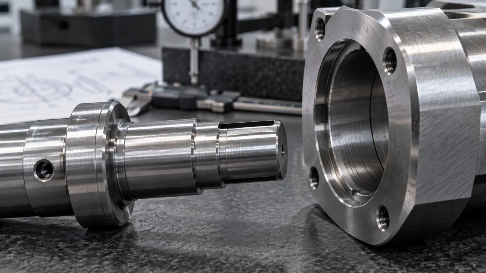
Why CNC Machined Parts Pass Inspection but Fail During Assembly
It is a frustrating scenario in precision manufacturing: a batch of parts passes incoming inspection against the drawing, yet CNC machining assembly problems appear when the components reach the production line. This disconnect between a verified dimensional inspection and a functional assembly failure often leads to production delays and costly rework.
When an isolated component measures within tolerance but still causes interference during final assembly, the root cause rarely lies in a single machining error. Instead, the problem usually stems from how individual dimensions interact in the physical world. Understanding this gap requires analyzing tolerance accumulation, geometric controls, and datum structures.
The Gap Between Dimensional Inspection and Functional Fit
Dimensional inspection verifies that a part matches the numerical values on a print in a static, unloaded state. A coordinate measuring machine maps points in space to confirm whether a diameter, length, or width falls within the allowable limits.
CMM inspection can verify dimensional and geometric requirements very effectively, but dimensional data alone may not fully represent functional assembly behavior when mating conditions, deformation, or worst-case tolerance interactions are involved. Functional assembly is a dynamic interaction. When mating components are joined, they introduce physical variables that a standard linear measurement might miss if the overall geometric envelope is not properly defined.
Common Causes of Assembly Failure in Machined Parts
Addressing assembly interference requires looking beyond individual part prints and examining the broader mechanical system. Several engineering factors contribute to these failures.
Tolerance Stack-Up Across Mating Components
Every machined feature has a tolerance, and when multiple parts are assembled, these individual variations accumulate. If multiple mating features approach their worst-case material conditions and the accumulated variation exceeds the available clearance, assembly interference can occur even when each individual feature remains within tolerance. Managing this requires analyzing the entire assembly sequence rather than just isolated part prints.
Misaligned Datum Relationships
Datums act as the foundational anchor points for manufacturing and inspection. If the datum structure on a drawing does not reflect how the part physically functions or mounts in its final assembly, the resulting component may be machined correctly relative to the wrong reference point. For example, if a part mounts on a specific functional flange, but the drawing uses a non-functional outer edge as the primary datum, the critical mating features may be misaligned during assembly.
Over-Relying on Linear Dimensions vs. GD&T
Linear tolerances (+/-) control size, but they do not adequately control shape, orientation, or location. Relying strictly on coordinate dimensions without applying Geometric Dimensioning and Tolerancing (GD&T) leaves critical form controls ambiguous. A hole might be the correct size and located at the correct X/Y coordinates, but if it is machined at a slight angle due to a lack of perpendicularity control, a mating pin will fail to insert properly.
Quality and Inspection Considerations for Assembly
To bridge the gap between static measurement and physical fitment, quality control strategies must align with functional requirements.
Dimensional and geometric inspection should be complemented by checks that reflect the actual functional relationship between mating components. Where appropriate, engineers may use functional gauges or assembly-specific inspection methods to evaluate fit under defined conditions. A functional gauge, such as a custom go/no-go fixture, is designed to mimic the mating component at its most restrictive condition. If a part physically fits into the functional gauge, it provides a physical check that it will assemble correctly on the production floor.
DFM Recommendations to Prevent Assembly Issues
Preventing assembly failures begins during the engineering phase. A thorough Design for Manufacturability (DFM) review helps identify and resolve interaction risks before machining begins.
- Establish Functional Datums: Select primary, secondary, and tertiary datums based on how the part mates and functions in the final assembly, rather than what is merely easiest to locate on a machine.
- Conduct Stack-Up Analysis: Perform worst-case and statistical tolerance analysis on all critical assemblies to identify potential interference risks.
- Apply GD&T Appropriately: Use geometric controls like position, profile, perpendicularity, and runout to define the functional boundaries of mating features.
- Communicate Mating Intent: Provide assembly models or explain the function of critical mating surfaces to your manufacturing partner so they can prioritize machining setups that protect functional fit.
Frequently Asked Questions
1. Why would a part measure correctly on a CMM but fail to assemble?A CMM can verify dimensional and geometric characteristics very effectively, but assembly fit may still be affected by tolerance stack-up, form error, datum relationships, or feature orientation. If the drawing lacks geometric controls (like straightness or perpendicularity), or if tolerance stack-up across multiple parts exceeds the assembly clearance, the parts will fail to fit despite being dimensionally in spec.
2. What is tolerance stack-up in CNC machining? Tolerance stack-up is the accumulation of dimensional variations across multiple mating components in an assembly. When individual tolerances combine, the total deviation can prevent the parts from fitting together properly.
3. How does GD&T help prevent assembly failures? GD&T controls the form, orientation, and location of features, not just their size. Controls such as position, profile, perpendicularity, and runout can define how critical mating features must relate to functional datums and to each other.
4. What is a functional gauge? A functional gauge is a custom physical inspection tool designed to simulate the mating component under its most restrictive tolerance conditions. It provides a physical check to verify assembly capability.
5. How should datums be chosen to improve assembly success? Datums should be selected based on the physical mating surfaces and functional alignment of the component in the final assembly.
6. Can parts be within tolerance and still not fit together? Yes. Individual dimensions may remain within tolerance while the combined effects of tolerance stack-up, datum relationships, form error, and feature orientation still create assembly interference.
Conclusion
When CNC machined parts pass inspection but fail on the assembly line, the issue is rarely a simple manufacturing error. It is often related to datum relationships, tolerance stack-up, or geometric requirements that do not fully represent the functional assembly condition. By aligning drawing specifications with real-world functional requirements and evaluating how components interact, engineering teams can reduce the gap between inspection results and successful mechanical assembly.
If your parts pass inspection but still create fit or assembly issues, an early DFM and tolerance review can help identify where the functional risk is coming from. You can share your drawing or assembly model to discuss critical mating relationships, tolerance stack-up, and manufacturability.