Oct 12, 2026CNC Machining
GD&T in CNC Machining: Beyond Size Tolerance
GD&T in CNC machining controls form, orientation, and location beyond size tolerance, so parts that pass inspection still fit and function in assembly.
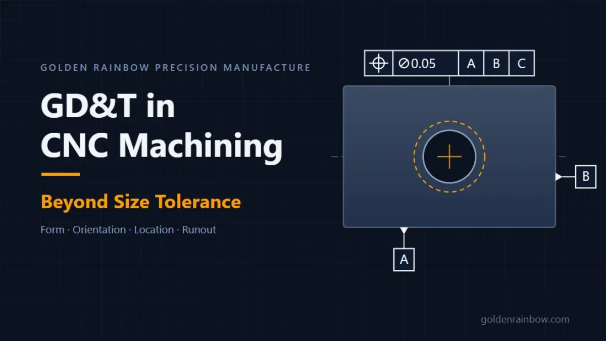
A hole can be the correct diameter. A shaft can be the correct size. Both parts can pass standard inspection. And they still may not fit together.
This is a common and frustrating scenario in precision manufacturing. When mechanical and design engineers investigate why CNC machined parts fail during assembly, they often discover that the root cause is not an incorrect diameter or width. The reason is that size alone does not control form, orientation, and location. Traditional plus/minus dimensions are useful for controlling feature size and linear relationships, but they may not fully define the geometric requirements needed for functional assembly.
To bridge this gap, engineers rely on Geometric Dimensioning and Tolerancing. Proper GD&T CNC machining practices clarify functional relationships, reduce ambiguity on the shop floor, and help ensure that mating components actually fit together in the real world.
Why Size Tolerance Alone Is Not Enough
A standard +/- dimensional tolerance is highly effective at controlling how large or small a specific feature can be. If a drawing specifies a diameter of 10 mm +/- 0.05 mm, the machinist knows exactly what the calipers or micrometers should read.
However, a size tolerance does not necessarily control the physical shape or orientation of that feature in 3D space. A cylinder can be within its diameter limits but still be slightly bowed. A surface can be the correct distance from an edge but still be wavy or tilted. Linear dimensions do not explicitly dictate straightness, flatness, perpendicularity, parallelism, position, profile, or runout. Without these geometric controls, a part can technically adhere to the numbers on a drawing while remaining geometrically unsuitable for its intended function.
How a Part Can Pass Inspection but Still Fail During Assembly
When drawings lack adequate geometric controls, ambiguities arise between manufacturing and assembly. Here are a few common engineering scenarios where this occurs:
- Hole diameter is correct, but the hole axis is not perpendicular: A bore is machined to the exact dimensional tolerance. However, the drill entered the material at a slight angle. When it is time to insert a long, tight-fitting mating pin, the pin binds because the hole lacks perpendicularity relative to the mating surface.
- Shaft diameter is correct, but form creates binding: A long shaft measures perfectly across its diameter at multiple discrete points. But because straightness was not controlled, the shaft has a slight curve (a banana shape). It will not pass through a tightly toleranced bushing.
- Bolt-hole pattern dimensions are correct but do not align functionally: The linear distances between four bolt holes are within tolerance. However, the entire pattern has shifted or rotated slightly relative to the outer functional edge of the part. The individual dimensions pass, but the pattern does not match the mating component.
Dimensional Tolerance vs. Geometric Tolerance
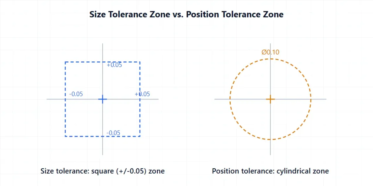
Understanding the distinction between these two systems is critical for effective drawing creation and drawing review.
- Primary function. Dimensional tolerance (+/-) controls feature size and linear distances. Geometric tolerance (GD&T) controls form, orientation, location, and runout.
- Tolerance zone. Dimensional tolerance is often a 2D rectangular or square area. Geometric tolerance is often a 3D boundary (for example, a cylindrical tolerance zone for holes).
- Datum dependency. Dimensional tolerance often implies relationships without defining a specific setup origin. GD&T explicitly requires a defined datum reference frame.
- Assembly impact. Dimensional tolerance is essential for defining fits (clearance, transition, interference). GD&T is essential for ensuring features align, mate, and function correctly.
Why Datum Selection Matters
In GD&T, a datum is a theoretical exact plane, axis, or point location that serves as a reference for other features. A datum reference frame typically consists of a primary datum, a secondary datum, and a tertiary datum, which lock the part's degrees of freedom in space.
The selection of these datums is critical. A functional datum represents how the part physically mounts, mates, or operates in its final assembly. If the drawing datum structure does not match how the part actually mounts, a part can be machined "correctly" relative to the wrong reference.
For instance, if a machinist uses a convenient, non-functional outer edge as a machining datum simply because it is easy to hold in a vise, the critical mating holes referenced from that edge will accumulate unnecessary variation.
GD&T Controls That Commonly Affect Assembly Fit
While the GD&T framework includes many symbols, a few key geometric controls are most frequently responsible for resolving assembly interference issues:
- Position: Controls where a feature (like a hole or a boss) is located relative to the datums. Position tolerance defines a geometric zone around true position and can represent mating-hole location more directly than separate X/Y coordinate tolerances in many assembly applications.
- Profile (of a Surface or Line): Controls the 3D boundary that a complex, curved, or freeform surface must fall within. It is essential for mating contoured parts.
- Perpendicularity: Perpendicularity controls how closely a surface or axis must remain oriented at 90 degrees relative to a datum within the specified tolerance zone. This is critical for preventing binding when inserting pins or shafts.
- Parallelism: Parallelism controls how closely a surface or axis must remain parallel to a datum within the specified tolerance zone, crucial for sliding components or stacked assemblies.
- Runout: Controls the variation of a surface as the part is rotated around a datum axis. This is heavily used for rotating shafts, gears, and turned components to prevent vibration and misalignment.
How GD&T Helps Manage Tolerance Stack-Up
Applying GD&T cannot magically eliminate CNC machining tolerance stack-up. Physical variations will always exist.
However, by utilizing functional datums and geometric tolerance zones (such as position and profile), engineers can manage how those variations accumulate. By reducing unnecessary chain dimensioning and referencing critical features to a shared functional datum reference frame, GD&T helps isolate variations. It clarifies the functional boundaries, ensuring that the calculated stack-up more accurately reflects real-world assembly conditions. For a focused walkthrough of accumulation mechanics and corrective practices, see our guide to CNC machining tolerance stack-up.
Quality and Inspection Considerations
Verifying geometric tolerances requires specialized equipment and a clear understanding of the drawing's intent.
A Coordinate Measuring Machine (CMM) can verify GD&T requirements effectively when the measurement strategy matches the drawing intent and datum structure. However, the resulting data depends heavily on the measurement strategy, point density, datum alignment, and the feature evaluation method. While CMMs provide highly accurate geometric data, engineers will sometimes complement CMM inspection with functional gauges (like a custom go/no-go fixture) or assembly-level validation to evaluate functional fit under defined worst-case mating conditions.
DFM Recommendations for GD&T Drawings
GD&T is a powerful tool, but it should be used to clarify function, not simply to make drawings more complicated. Consider these Design for Manufacturability (DFM) guidelines:
- Use Functional Datums: Align your datums with the physical surfaces that actually dictate the part's orientation in the final assembly.
- Avoid Unnecessary Geometric Controls: Do not apply a perpendicularity or flatness callout if a standard size tolerance adequately covers the functional requirement.
- Do Not Over-Tighten Every Tolerance: Use GD&T to allow more tolerance where possible (such as taking advantage of bonus tolerance with MMC modifiers on position).
- Identify Critical-to-Function Features: Clearly indicate which geometric relationships are non-negotiable for assembly.
- Share Assembly Context with Your Manufacturing Partner: Allowing your machine shop to see the assembly CAD helps them align their machining and inspection references with your functional intent.
- Review Real Failure Modes: Our guide to CNC machining assembly problems shows how unchecked geometric, tolerance, and datum variation surfaces when parts reach assembly.
Common GD&T Mistakes
Even experienced teams can encounter issues when drafting or interpreting GD&T. Common mistakes include:
- Using non-functional datums that are easy to measure but irrelevant to the assembly.
- Over-tolerancing by applying overly restrictive geometric controls on non-critical surfaces.
- Missing orientation control, assuming a size tolerance will keep a deep hole perfectly straight.
- Relying only on coordinate dimensions for complex bolt-hole patterns.
- Applying conflicting tolerance callouts (for example, setting a position tolerance tighter than the feature's size limits can support).
- Leaving the inspection intent unclear by failing to specify how datums should be simulated.
Frequently Asked Questions
1. What is the difference between dimensional tolerance and GD&T?
Dimensional tolerance (+/-) controls the size of a feature and linear distances. GD&T (Geometric Dimensioning and Tolerancing) controls the form, orientation, location, and runout of features relative to a defined datum reference frame.
2. Can a part be within size tolerance and still fail assembly?
Yes. A hole or shaft may be the exact correct diameter, but if it lacks geometric controls for straightness, perpendicularity, or position, it may be angled or bowed in a way that prevents it from mating with other components.
3. How does position tolerance affect hole alignment?
Position tolerance establishes a precise geometric zone (usually cylindrical) around true theoretical center. This defines the allowable shift of a hole's axis within a specific boundary, providing a clear functional envelope that helps ensure bolt patterns align correctly with mating parts, compared to the rectangular zones created by X/Y coordinate tolerances.
4. Why are functional datums important?
Functional datums represent the actual physical surfaces where the part mates or mounts in its final assembly. Using functional datums ensures the part is manufactured and inspected relative to how it actually works in the real world.
5. Does GD&T reduce machining cost?
When applied appropriately, it can. GD&T can better reflect the actual function of a part. By clearly defining geometric boundaries and allowing for functional tolerance zones, it often provides machinists with usable tolerance where it matters, which may help avoid unnecessarily restrictive manufacturing requirements and reduce avoidable rework in some applications.
6. How does GD&T relate to tolerance stack-up?
While GD&T does not eliminate physical variation, using functional datums and explicit geometric controls prevents tolerances from accumulating unpredictably. It allows engineers to calculate and manage stack-up based on true functional relationships.
Conclusion
Size tolerance alone does not fully define functional geometry. While standard linear dimensions are critical for establishing basic sizes, successful assembly often depends on how size, orientation, location, form, and datum relationships work together as a complete system. By strategically applying GD&T, engineering teams can reduce ambiguity on the shop floor, align inspection methods with actual physical requirements, and reduce the risk of assembly interference.
If you are working with mating components or drawings that include critical geometric relationships, an early DFM and tolerance review can help identify potential assembly risks before production begins. You can share your drawing or assembly model with us to discuss datum strategy, GD&T requirements, and manufacturability. Golden Rainbow supports precision CNC machining projects with drawing review and DFM discussions focused on manufacturability and assembly risk.